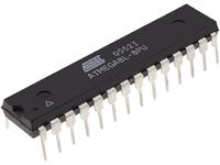
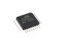
XenoGC Clone
Overview
The XenoGC is a Drivechip for the Nintendo Gamecube which utilizes an Atmega8L microcontroller to interface with the debug communications port 'CN302.'
A homebrew version (clone) of the XenoGC can be built with the same Atmega8L microcontroller and a few additional components.
Features
The XenoGC Clone allows all the same features as the original XenoGC
   * Direct boot of DVD+-RW media
   * Compatible with all regions & all versions
   * Region free loading
   * Super easy wireless install
   * No need to remove mainboard
   * PAL/NTSC region force
   * Installation control LEDs
   * Switchable read setting adjustment / error retry
   * Switchable audiofix
   * Extremely low cost (to build)
Additional Features
   * DVD Disc upgradeable               ( Requires Bootable Disc for Xeno DOL Flashing Utility )
   * Network upgradeable                ( Requires BBA Adapter and Xeno DOL Flashing Utility )
   * SDcard upgradable                  ( Requires SD Gecko and Xeno DOL Flashing Utility )
   * Serial/Parallel ISP upgradable     ( Requires AVRdude or similar software and XenoGC Clone - ISP board version )
   * Load ISO from Network              ( Requires Third Party App )
   * Backup Game via Network            ( Requires Third Party App )
   * Supports multi-game discs          ( Game Compilations on One Disc )
   * Supports Action Replay cheat codes ( Requires Action Replay Disc )
Settings
The XenoGC Clone allows the same settings as the original XenoGC
| Button | Description |
|---|---|
| [L button] Disable audiofix | Disable Native Audiofix to support modified backup images created for a BIOS which did not support Streaming Audio data. |
| [R button] Disable DREfix | Disable Native Disc Read Adjustment and Read Retries. Uses default read settings to scan a disc for read errors. |
| [X/Y button] Force NTSC/PAL | Force Region display mode regardless of the game region. |
| [START button] Miscellaneous Function | Version 1.01.V2 - Display Software Version, GC Revision, Drive Version, Special Message. |
| Version 1.03a.V1 - Display Software Version, GC Revision, Drive Version, Special Message | |
| Version 1.04 - Multi-Game Shell Version 0.98b (PAL) (Not Multi-Disc Games) | |
| Version 1.05 - Multi-Game Shell Version 1.05 (PAL) (Not Multi-Disc Games) | |
| Status LEDs | Red LED is active during Drive Reset and delivery of Drive Code. |
| Green LED is activated after successful Drive Code execution. | |
| NOTE: XenoGC 2.0 and Counterfeits might have Orange LED instead of Green. | |
| NOTE: Check installation if no LED activity or constant Red LED. |
Building the Board
Multiple considerations must be taken into account prior to building a XenoGC Clone.
These considerations for choosing a board design include:
   * Intended usage of the product ( standard user or developer/advanced tester )
   * Limitation differences between the two boards regarding Firmware Update Methods
   * Target microcontroller type
   * User's own abilities or willingness to learn
Board Design
A standard (typical) user can choose to build the basic XenoGC Clone board design which offers the same abilities as the original XenoGC. A developer or advanced tester may choose to build the basic Clone as well, but may benefit from the XenoGC Clone - ISP design which offers the additional ability to program the board via ISP serial/parallel programmer.
Programming Requirements
Since the XenoGC Clone is limited to the original design, the only method of updating firmware is to utilize a prepared Xeno DOL Flashing Utility which contains a firmware update. Like the XenoGC, the Clone will require a switch which sets the microcontroller into program mode by making contact between RESET and GND. Firmware Corruption Recovery Methods are limited to this board design and require the user to perform one of the following:
   * Desolder the board and manually reprogram the microcontroller via Serial/Parallel ISP.
   * Utilize an Alternate DOL loading method to reprogram the chip via Xeno DOL Flasher Utility
To work around the limitation of recovery which most likely occurs during developing, a developer or advanced tester should choose to build the XenoGC Clone - ISP. This board design offers the flexibility to program the microcontroller utilizing the Xeno DOL Flashing Utility or ISP updates ( design compensates so ISP communicates without data conflict from port CN302 ). Like the XenoGC, the Clone - ISP will require a switch between RESET and GND only when updating via Xeno DOL Flashing Utility. For ISP updates, program mode is achieved when the ISP to connected to the microcontroller.
It should be noted that a blank Atmel chip cannot be programmed fully by the DOL Flashing Utility, however, as the .DOL will not program the 'fuses' of the Atmel chip. This means that the initial programming must be done via a PC-style programmer.
Atmega8 vs Atmega8L vs Atmega8A
Both the Atmega8 and Atmega8L can be used to create a fully functional XenoGC clone. The two versions of this microcontroller have a difference in power requirements and operational speed which do not interfere in the performance during code execution. Due to END OF LIFE of the Atmega8 and Atmega8L, Atmel created the Atmega8A as a direct drop in replacement. The Atmega8A (Farnell link) has also been observed to work with the provided firmware images.
Power Requirements
Power requirements should be considered prior to the purchase, creation, and installation of a XenoGC clone. The Atmega8L can be powered directly with 3.3v from the serial debug port CN302, as per original XenoGC design. However, the Atmega8 requires a higher 4.5v - 5.5v voltage input which will have to be provided from elsewhere on the motherboard.
Atmega8L Manufacturer Flaw
Per Atmel datasheet, the original design of the XenoGC includes two 0.1uF capacitors: 1. between VCC and GND 2. between AVCC and GND
Testing of the Atmega8L DIP 28P3 package style microcontroller, there exists ~5 ohms difference between AVC and AVCC with continuity found between the pins. Whereas, the Atmega8 indicates a difference of ~550K ohms between AVC and AVCC with no continuity. Based on this data, the XenoGC Clone and XenoGC Clone - ISP board designs are presented for the use of an Atmega8L using only a single 0.1uF capacitor. If an Atmage8 is the target microcontroller, a second 0.1uF capacitor may be required (which is not displayed in the Clone schematics).
Operational Speed
At 3.3v, the ATmega8L and the ATmega8A can run at 8 MHz, while at 5.0v, the ATmega8 and the ATmega8A can run at 16 MHz. However, this is not a concern since the XenoGC was based on the ATmega8L running at 8 MHz. Furthermore, no increase in performance has been noted during testing of the ATmega8L and the ATmega8 at their maximum speeds.
Microcontroller Specifications
| ATMEGA8L | Speed (MHz) | Power Supply (V) | Code | Package |
|---|---|---|---|---|
| 0 - 8 | 2.7 - 5.5 | Atmega8L-8AU | TQFP 32A | |
| Atmega8L-8AUR | ||||
| Atmega8L-8PU | PDIP 28P3 | |||
| Atmega8L-8MU | MLF (VQFN) 32M1-A | |||
| Atmega8L-8MUR | ||||
| ATMEGA8 | ||||
| 0 - 16 | 4.5 - 5.5 | Atmega8-16AU | TQFP 32A | |
| Atmega8-16AUR | ||||
| Atmega8-16PU | PDIP 28P3 | |||
| Atmega8-16MU | MLF (VQFN) 32M1-A | |||
| Atmega8-16MUR | ||||
| ATMEGA8A | ||||
| 0 - 16 | 2.7 - 5.5 | Atmega8A-AU | TQFP 32A | |
| Atmega8A-AUR | ||||
| Atmega8A-ANR | ||||
| Atmega8A-PU | PDIP 28P3 | |||
| Atmega8A-PN | ||||
| Atmega8A-MU | MLF (VQFN) 32M1-A | |||
| Atmega8A-MUR | ||||
| Atmega8A-MNR |
XenoGC Clone
Basic Clone of the original XenoGC. This design will function in all aspects to the original XenoGC. Firmware updates are limited to Xeno DOL Flasher Utility with a standard on/off switch between RESET and GND to set the microcontroller into program mode.
Parts List
| QTY | COMPONENT |
|---|---|
| 1 | Atmega8L-8PU |
| 1 | 0.1uF Capacitor |
| 1 | 1K ohm Resistor |
| 2 | 220 ohm Resistor |
| 1 | Red LED |
| 1 | Green LED |
Diagrams
| Clone Pictorial Diagram | 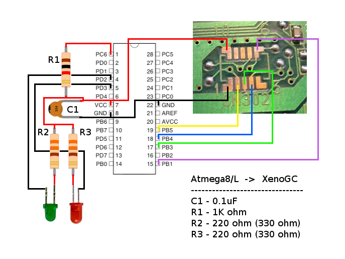
|
|---|---|
| Clone Circuit Diagram | 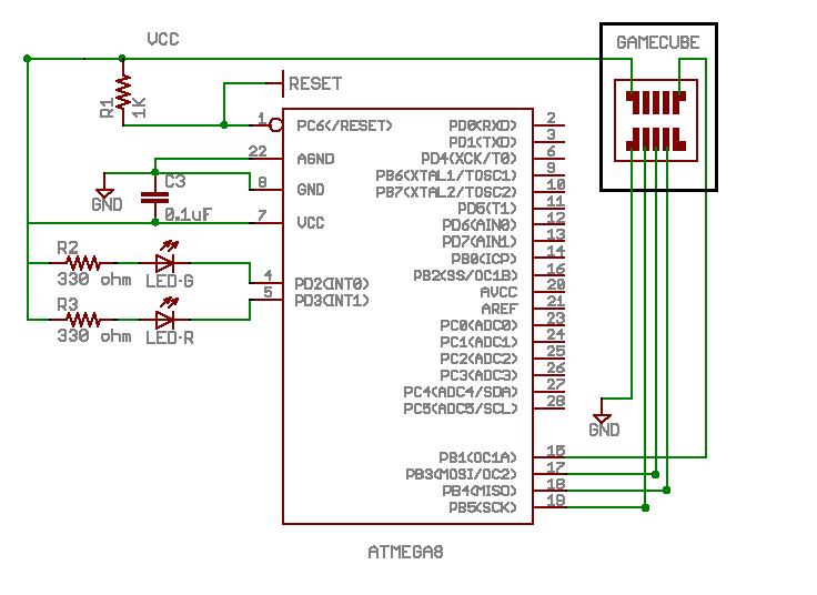
|
Programming and Updating
Firmware updates can only be accomplished using a prepared Xeno DOL Flasher Utility with on-screen instructions. This method of firmware updating can be considered safe, however if a corrupted write occurs (ie, power loss) there exists only a few limited options for chip recovery which include one of the following methods:
   * Desolder the board and manually reprogram the microcontroller via Serial/Parallel ISP.
   * Utilize an Alternate DOL loading method to reprogram the chip via Xeno DOL Flasher Utility.
XenoGC Clone - ISP
Same as the basic Clone with added ability to update firmware using both Xeno DOL Flasher Utility or Serial/Parallel ISP. This design will function in all aspects to the original XenoGC. A standard on/off switch between RESET and GND is required to set the microcontroller into program mode only when using Xeno DOL Flasher Utility.
Parts List
| QTY | COMPONENT |
|---|---|
| 1 | Atmega8L-8PU |
| 1 | 0.1uF Capacitor |
| 2 | 1K ohm Resistor |
| 1 | 100 ohm Resistor |
| 2 | 220 ohm Resistor |
| 1 | Red LED |
| 1 | Green LED |
Diagrams
| Clone ISP Pictorial Diagram | 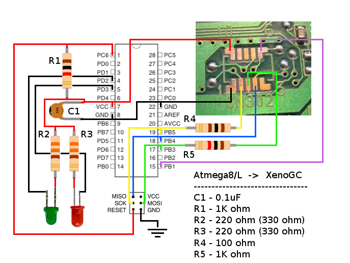
|
|---|---|
| Clone ISP Circuit Diagram | 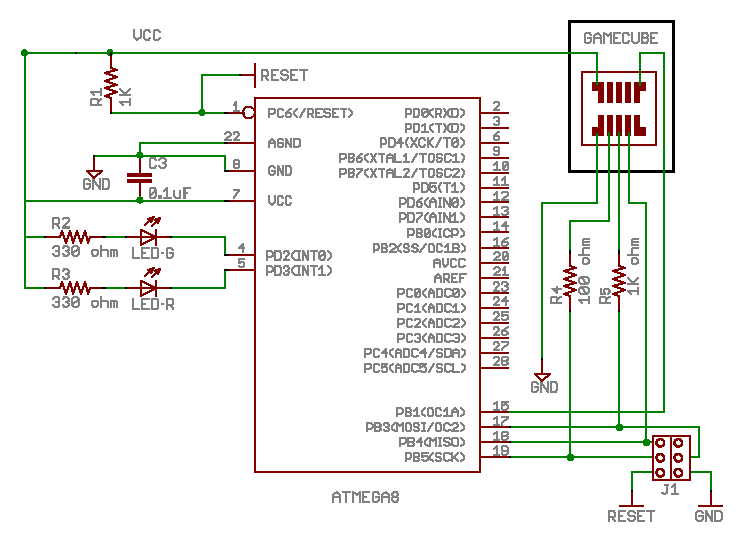
|
| XenoGC Clone with ISP headers (wired) | 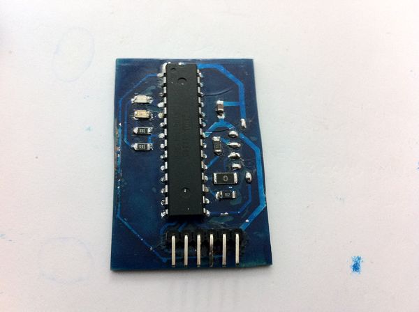
|
| XenoGC Clone with ISP headers (wireless) | 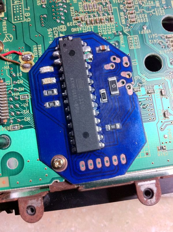
|
Programming and Updating
Firmware updates can only be accomplished using a prepared Xeno DOL Flasher Utility with on-screen instructions or thru the use of a Serial/Parallel ISP and AVRdude (or similar software). This design offers the most flexible method for developers or advanced testers to quickly load and verify results of code changes while also offering the ability to recover the microcontroller due to unexpected code results.
Building a Low Cost Programmer
A low cost programmer is essential for everyone; standard users, advanced testers or developers. The most essential function of a programmer is to allow communication with the microcontroller's bootloader to write new code, set fuses, or recover from a corrupted flash. A programmer is easy to build, very low cost, and recommended for any and all who wish to build their own XenoGC Clone. Every programmer has a name (or Device type) which is required for the programming software to set the proper communication protocol.
Serial Programmer
Device Type: ponyser
Parts List
| QTY | COMPONENT |
|---|---|
| 1 | DB9 Serial Connector |
| 2 | 4.7K ohm Resistor |
| 1 | 10K ohm Resistor |
| 1 | 15K ohm Resistor |
| 2 | 5.1V Zener Diode |
| 1 | BC547 NPN Transistor |
Circuit Diagrams
| Serial Programmer Pictorial Diagram | 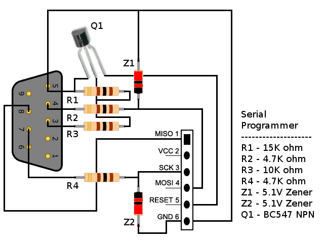
|
|---|---|
| Serial Programmer | 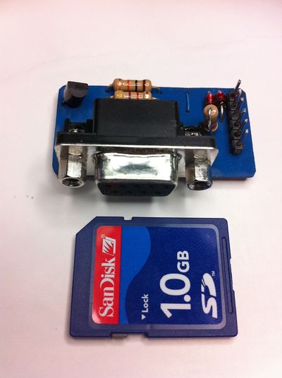
|
Parallel Programmer
Device Type: sp12
Parts List
| QTY | COMPONENT |
|---|---|
| 1 | DB25 Parallel Connector |
| 7 | 220 ohm Resistor |
| 1 | 47 uF Capacitor |
Circuit Diagrams
| Parallel Programmer Pictorial Diagram | 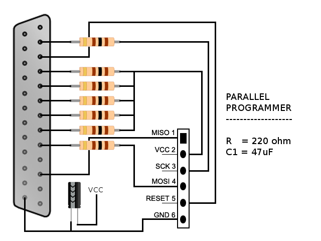
|
|---|
USB Programmer
Device Type: usbtiny
Note: required Avrdude 5.5 or greater.
Works with linux, mac, windows. Admin permissions may be required for linux/mac
Attiny2313-20mhz version only, 10mhz incompatible. Also, IC must be preprogrammed with USBtiny flash software. External 3.3v / 5v power recommended, USB may not provide adequate power.
Parts List
| QTY | COMPONENT |
|---|---|
| 1 | Attiny2313 -20p |
| 1 | 12mhz crystal |
| 2 | 27pF capacitors |
| 1 | 0.1uF capacitors |
| 5 | 1.5K ohm resistors |
| 2 | 27 ohm resistors |
| 2 | LEDs |
| 2 | 3.3v / 3.6v zener diode |
| 1 | usb connector female |
Circuit Diagrams
| USB Programmer Pictorial Diagram | 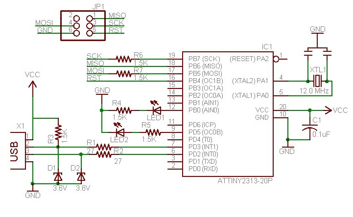
|
|---|---|
| USBtiny Programmer with optional onboard power supply | 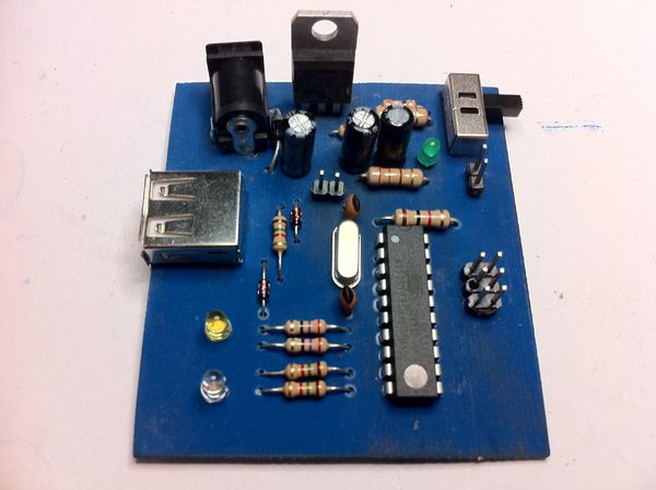
|
Programming Software
The most convenient form of software updating is the Xeno DOL Flashing Utility.
However, utilizing a Serial/Parallel ISP is beneficial with software, such as AVRDUDE, which allows writing, reading, and erasing of the Flash, as well as, reading and setting fuses via command line function. AVRDUDE offers support for Serial, Parallel, and USB programmers.
Quick Programming Reference
| FUNCTION | COMMAND |
|---|---|
| WRITE | /usr/bin/avrdude -p m8 -c ponyser -P /dev/ttyS0 -v -U flash:w:XenoAT.1.05.hex:i |
| SET FUSES | /usr/bin/avrdude -p m8 -c ponyser -P /dev/ttyS0 -v -U lfuse:w:0x84:m -U hfuse:w:0xD9:m |
| READ FUSES | /usr/bin/avrdude -p m8 -c ponyser -P /dev/ttyS0 -U hfuse:r:-:r -U lfuse:r:-:r |
Technical Note Regarding Fuse Settings
According to the ATMega8/8L's datasheet (Table 10. Pg 30,) enabling the "Brown Out Detection" (BOD) bit is recommended when using the internal 8Mhz oscillator at minimum startup time. The recommended lfuse setting is 0x84 (BOD enabled.) (Source)
Source Code
In February 2011, the source code was made publicly available at GC-Forever
- Within the source code package are compiled .HEX files which can be used to program XenoGC/Atmega8 microcontroller with an ISP programmer. Additionally, xenoflasher.dol files are also included as a standalone method to natively program the XenoGC/Atmega8 using the existing Gamecube interface.
Included HEX & DOLS
| File Type | Location | Name | Status | Start Button Action | md5sum |
|---|---|---|---|---|---|
| HEX | Root Directory | XenoAT.1.05.hex | Works | PAL ONLY Shell | 1381b07513bb22fd701245ad2457c23e |
| /Drivecode/Source/1.03a/ | XenoAT.hex | Non-functional | -- | 727d860899916f067c1a496e739a29a7 | |
| /XenoAT/Bin/ | XenoGC 1.01.V1.hex | Non-functional | -- | 08318c75b45eccc9eb3ad78fa0a25cf9 | |
| XenoGC 1.01.V2.hex | Works | NTSC/PAL Credits | a6ba8066467ef568c2f8f36c0ec97b89 | ||
| XenoAT.1.03.v1.hex | Non-functional | -- | f6ddb4faf6d0247ee460a351b15a8499 | ||
| XenoAT.1.03a.v1.hex | Works | NTSC/PAL Credits | e572a5994c118680d406d254072cf19a | ||
| XenoAT.1.03a.v2.hex | Non-functional | -- | f6ddb4faf6d0247ee460a351b15a8499 | ||
| XenoGC 1.04.hex | Works | PAL ONLY Shell | ea65af9e421a890fb980d564f3f88e9d | ||
| XenoAT.hex | Works | PAL ONLY Shell | 1381b07513bb22fd701245ad2457c23e | ||
| XenoFlash DOL | Root Directory | xenoflash.1.05.dol | Works | 3abe3ea0d60333d998b8e9730881dd76 | |
| /XenoFlash/Bin/ | xenoFlash.1.01.dol | Works | 656ee973233cbd19afdece8f7053315a | ||
| xenoFlash.1.04b.dol | Works | 92d0ae36375eb6beee6e5ac495eb3a25 | |||
| xenoflash.dol | Works | 3abe3ea0d60333d998b8e9730881dd76 |
GoogleCode Project
Developers, please feel free to contribute @ GoogleCode Project
Compiler Requirements
WINDOWS
1. Download and install verified working compiler - WinAVR 20050214
2. Edit Makefile as necessary to include your WinAVR Path
3. Open CMD prompt and change directory to YourLocation/XenoGC-Source/XenoAT
4. Type make
LINUX
gcc 3.4 is recommended to compile the following source packages for both AVR and MN10200.
Note: Using newer versions of gcc may cause compile failures!!
    avr-libc-1.2.3
    binutils 2.15-3
    gcc-2.95.3
    gcc-3.4.3
The required sources have been pre-packaged as XenoTools available at the googlecode xenogcfork page. Compile instructions can be found HERE
MAC
to be continued...maybe (anyone got a MAC??)
| XenoGC Clone | |
|---|---|
| Developers | Open Source |
| CPU | Atmel Atmega8L |
| Modchip Type | Drivechip |
| Features | Gamecube BIOS |
| Installation | 0 wires (optional 6 wires) |
