Gamecube component cable

Portables, case replacements, mods etc, all in here!
Locked
Durgan
Posts: 21
Joined: Tue Apr 19, 2011 10:00 am

Re: Gamecube component cable

Post by Durgan » Mon Jan 23, 2012 10:51 pm

emu_kidid wrote:Durgan, you basically just write values to the register block mentioned here: http://gc-forever.com/yagcd/chap5.html#sec5.3

In libOGC this is all done transparently in VIDEO_Init() and VIDEO_Configure(mode);
What place is best to learn about how to do that?


Also, what exactly is a register? Is it a string of bits, a value, a title given to a variable (so humans can recognize it)?

Also, do you know where these are stored physically? And are all of the registers in the GC stored in the same place (besides being in different blocks)?
User avatar
megalomaniac
Posts: 2480
Joined: Sun Aug 21, 2011 5:33 am
Location: Drunk in Texas
Contact:

Re: Gamecube component cable

Post by megalomaniac » Tue Jan 24, 2012 12:00 am

so ....
there are two different video chips between PAL and NTSC..
this means the output traces from the AVE to analog video port (pin 25 vs pin23) are different on the mobo between PAL and NTSC...(nice i didnt know that)
since the ycbcr signal passes directly from flipper to the digital port while also feeding the AVE, then the MX B012355 should be able to directly connect to flipper and remove the AVE...on both NTSC and PAL...video only..not talking about audio encoding the AVE also does...Ashen, does this mean you can chop the board smaller now???


i dont know if there are any DOL-101 sanded pics to compare the traces vs DOL-001...but with the current issues, it might not even be necessary to pinout or compare traces.


on a DOL-001 running in standard interlaced mode, video will display from both analog and digital port. once progressive is selected, then analog video drops out because the AVE cannot adjust to 54mhz frequency (no 54mhz signal to the AVE)

on a DOL-101 running in standard interlaced mode, video would not display on analog or digital port..at a minimum, video should be displayed..
when the unit is powered on, the GC intro can be heard playing (no video from any port). If no disc is in the drive, i should at least hear the tone as the GC goes into the main menu. No tone was heard. Controller functions could not be heard either (if i was in the main menu).
my assumption is the behavior appeared typical of when booting the system and receiving an error message on screen and the system halts.
if the ycbcr data can be passed thru, then (possibly) why did the system detect a fault in interlaced mode...(IPL???)


the bigger issue is: even if we could get video to display thru the MX chip in interlaced mode, i could not identify a 54mhz clock on the DOL-101. Since the MX chip and the RTC chip require 54Mhz to display progressive mode, the lack of this clock will not allow progressive mode... Also, on the DOL-101, the RTC clock input is connected to 27mhz, unlike on the DOL-001 which the RTC is connected to 54mhz.


and once again, the IPL...
it appears there is no hardware compatibility for progressive mode..i would assume the progressive mode feature was removed from the IPL also...if the IPL still supports progressive mode, then that option can never be selected for lack of a 54mhz signal and will only cause a loss of video..
If a successful video connection was established and displayed on a DOL-101 using an MX chip in interlaced mode only, then the only improvements will be better color spacing and slightly improved/sharper resolution (similar to a RGB PAL), but nothing close to improvements compared to progressive mode.
emu_kidid wrote: beer is like WD40 for megalomaniac's brain, gets the gears moving
>>> BadAssConsoles.com <<<

Image Image Image
Durgan
Posts: 21
Joined: Tue Apr 19, 2011 10:00 am

Re: Gamecube component cable

Post by Durgan » Tue Jan 24, 2012 4:02 am

Well since you don't need near as many connections for the DAC, you could just hook it up separately from the mobo (for the audio). Just make sure it's insulated from anything it touches.
megalomaniac wrote: on a DOL-001 running in standard interlaced mode, video will display from both analog and digital port. once progressive is selected, then analog video drops out because the AVE cannot adjust to 54mhz frequency (no 54mhz signal to the AVE)

on a DOL-101 running in standard interlaced mode, video would not display on analog or digital port..at a minimum, video should be displayed..
when the unit is powered on, the GC intro can be heard playing (no video from any port). If no disc is in the drive, i should at least hear the tone as the GC goes into the main menu. No tone was heard. Controller functions could not be heard either (if i was in the main menu).
my assumption is the behavior appeared typical of when booting the system and receiving an error message on screen and the system halts.
if the ycbcr data can be passed thru, then (possibly) why did the system detect a fault in interlaced mode...(IPL???)
Are these experiments of hooking up a MX chip to the GC internal DAC?

In the case of each board do you have both DACs hooked up at once? Maybe the second case is similar to trying to hook up a WKF and disc drive simultandously. Maybe the Flipper doesn't put out enough current to drive both. In the first case, the internal DAC might just shut itself off (go transparent) if it doesn't detect an interlaced signal, as opposed to taking in the data and just not working.

Also, it looks like there are some filter capacitors or something in line from the internal DAC to the digital port. Don't know how non-crucial those are.
megalomaniac wrote: the bigger issue is: even if we could get video to display thru the MX chip in interlaced mode, i could not identify a 54mhz clock on the DOL-101. Since the MX chip and the RTC chip require 54Mhz to display progressive mode, the lack of this clock will not allow progressive mode... Also, on the DOL-101, the RTC clock input is connected to 27mhz, unlike on the DOL-001 which the RTC is connected to 54mhz.


and once again, the IPL...
it appears there is no hardware compatibility for progressive mode..i would assume the progressive mode feature was removed from the IPL also...if the IPL still supports progressive mode, then that option can never be selected for lack of a 54mhz signal and will only cause a loss of video..
If a successful video connection was established and displayed on a DOL-101 using an MX chip in interlaced mode only, then the only improvements will be better color spacing and slightly improved/sharper resolution (similar to a RGB PAL), but nothing close to improvements compared to progressive mode.
Yeah, for progressive it looks like you'd have to add a 54 MHz clock AND modify the GC's code for rev C boards, if it's even possible at all. But even interlaced component sounds pretty nice when compared with composite.
User avatar
Ashen
Posts: 994
Joined: Tue Nov 16, 2010 3:08 pm

Re: Gamecube component cable

Post by Ashen » Tue Jan 24, 2012 5:37 am

I don't think cutting the motherboard any smaller than we do already would really be practical. Its always been possible though, you'd need to rewire a bunch of critical stuff to do it. ARAM chip, timing crystals, RTC chip, etc.
User avatar
megalomaniac
Posts: 2480
Joined: Sun Aug 21, 2011 5:33 am
Location: Drunk in Texas
Contact:

Re: Gamecube component cable

Post by megalomaniac » Tue Jan 24, 2012 6:49 pm

Durgan wrote: Are these experiments of hooking up a MX chip to the GC internal DAC?
Yes, I used my MX dev board to connect the MX to all required points on the DOL-101 just as I have done in the past using the same dev board wired to a DOL-001
Durgan wrote: In the case of each board do you have both DACs hooked up at once? Maybe the second case is similar to trying to hook up a WKF and disc drive simultandously. Maybe the Flipper doesn't put out enough current to drive both.
Yes, both MX and AVE are hooked up at the same time...as per nintendo design on the DOL-001, both analog and digital cables are suppose to be connected at the same time..this does not appear to be related to the WKF dual connection.

Durgan wrote:In the first case, the internal DAC might just shut itself off (go transparent) if it doesn't detect an interlaced signal, as opposed to taking in the data and just not working.
The AVE does not really shut itself off...it detects the video mode and stops displaying data when progressive mode is selected, but still processes audio. So its always on.

Durgan wrote: Also, it looks like there are some filter capacitors or something in line from the internal DAC to the digital port. Don't know how non-crucial those are.
those appear to be a bank or ferrites. If anything, they would only affect video quality, but most likely are only for circuit protection from ESD.
Durgan wrote: Yeah, for progressive it looks like you'd have to add a 54 MHz clock AND modify the GC's code for rev C boards, if it's even possible at all.
I have not traced all possible points to determine what all mobo components require 54mhz signal. If we could connect this signal to all required points, then we might still need a compatible IPL. There was discussion on IRC about loading a substitute official IPL for quick testing. This would be easier than modifying the GC RevC IPL.
Now that I think about about it a bit more, Qoob (or was it viper??), IPL releases had some confusion about which IPL was required for each unit. If a modified IPL could not be made into a universal solution, then maybe a substitute official IPL might not be compatible either.
Maybe someone with more knowledge of the IPL can clarify.
Durgan wrote: But even interlaced component sounds pretty nice when compared with composite.
Yes, there are very noticeable improvements, the unfortunate issue is "currently" it would still require the MX chip.
emu_kidid wrote: beer is like WD40 for megalomaniac's brain, gets the gears moving
>>> BadAssConsoles.com <<<

Image Image Image
Durgan
Posts: 21
Joined: Tue Apr 19, 2011 10:00 am

Re: Gamecube component cable

Post by Durgan » Wed Jan 25, 2012 6:35 am

Or the Wii's encoder perhaps, as Ashen suggested. The idea has crossed my mind as well, though I haven't looked into it yet. I'm interested to though because I'm probably going to use a Wii for a portable I want to make.

I can't think of anything that might be different in the signal for the DOL-101 model. Maybe the output pinout is different? If the YCbCr coming out of the flipper on a DOL-001 is the same as the YCbCr coming out of the flipper on a DOL-101, then it should just work, simple as that. It shouldn't matter which chip is receiving it. You're sure there are no bridges/shorts or anything like that and that everything else normally connected to the MX chip is in place? And that the board works normally? I'm just trying to go over everything and figure out what could possibly be wrong.

I couldn't see everything, but in the pic you posted before, it looked like you had three encoders hooked up: the internal DAC, your proto board (I assume that's where the wires were going), and an official component cable plugged into the digital port. Just to clarify, that was the one you said worked, right? Can you still not get it to work on a DOL-101?

I know the WKF is not related, I was just thinking of what appeared to be a similar type of problem.
Durgan
Posts: 21
Joined: Tue Apr 19, 2011 10:00 am

Re: Gamecube component cable

Post by Durgan » Sun Jan 29, 2012 2:55 am

I figure I'll hold off on making the thread I mentioned before until after the above mods/questions are better understood.

In the meantime, I've been trying to find out more about the software side of the GC. But I've been having trouble finding "introductory" information on the GameCube's code and how all these pieces talked about fit together and exactly what each one is/what it does. Is there another place I can look to to start from the basics? For now I'll go back to searching.
Durgan wrote:
emu_kidid wrote:Durgan, you basically just write values to the register block mentioned here: http://gc-forever.com/yagcd/chap5.html#sec5.3

In libOGC this is all done transparently in VIDEO_Init() and VIDEO_Configure(mode);
What place is best to learn about how to do that?


Also, what exactly is a register? Is it a string of bits, a value, a title given to a variable (so humans can recognize it)?

Also, do you know where these are stored physically? And are all of the registers in the GC stored in the same place (besides being in different blocks)?
User avatar
megalomaniac
Posts: 2480
Joined: Sun Aug 21, 2011 5:33 am
Location: Drunk in Texas
Contact:

Re: Gamecube component cable

Post by megalomaniac » Sat Feb 04, 2012 4:58 am

Durgan wrote:I figure I'll hold off on making the thread I mentioned before until after the above mods/questions are better understood.

In the meantime, I've been trying to find out more about the software side of the GC. But I've been having trouble finding "introductory" information on the GameCube's code and how all these pieces talked about fit together and exactly what each one is/what it does. Is there another place I can look to to start from the basics? For now I'll go back to searching.

for the software side, check out the libogc examples...
hello world is always a good place to start with learning the basics for gamecube such as initialize video, background color, printf, printf w/color...
emu_kidid wrote: beer is like WD40 for megalomaniac's brain, gets the gears moving
>>> BadAssConsoles.com <<<

Image Image Image
User avatar
megalomaniac
Posts: 2480
Joined: Sun Aug 21, 2011 5:33 am
Location: Drunk in Texas
Contact:

Re: Gamecube component cable

Post by megalomaniac » Sat Feb 04, 2012 6:04 am

so as i last stated i would post pics of possible board designs to be soldered into a removed digital port...
well, things have changed....so here are a few updates


im currently in process of designing and almost testing a digital port connector...external connector similar to the original nintendo design...with some obvious differences of course..
i am under a timeline since i requested vacation time off to focus exclusively on production of the boards scheduled for Feb 13 -17.
I may change my vacation time to the week after if i have not yet completed final designs...but production will begin sometime this month...because i want to END this project !! :)

just to reiterate, the final product will contain:
component video connector
vga connector
FO toshlink connector
switch (VGA/Component)

I have designed, redesigned, scrapped design, new designed, and redesigned many many times over in order to develop the best possible board layout to keep this project as small as possible. however, one thing i cannot change is the size of the connectors and switch. the final product will be as small as i can successfully produce but the final size will be limited to the width, height and length of these other components.

With that in mind, i cutout a piece of foam with my anticipated final size for a quick and dirty demonstration for visual purposes only...

ImageImage
Image

ImageImage

Image


wow, so i was writing this post as i was taking these photos...
now that i look at that last pic compared to the original connector, maybe its not as big as i thought afterall...
i will still need to make a custom vacuform housing after end of board production..maybe i can shape and curves for an improved appearance...

this is still an ongoing work in progress with changes happening everyday...
hell...changes are happening every minute...
i just hope the final design size will indeed end up as anticipated and displayed in these photos...
emu_kidid wrote: beer is like WD40 for megalomaniac's brain, gets the gears moving
>>> BadAssConsoles.com <<<

Image Image Image
Durgan
Posts: 21
Joined: Tue Apr 19, 2011 10:00 am

Re: Gamecube component cable

Post by Durgan » Sun Feb 05, 2012 2:23 pm

megalomaniac wrote:
Durgan wrote:I figure I'll hold off on making the thread I mentioned before until after the above mods/questions are better understood.

In the meantime, I've been trying to find out more about the software side of the GC. But I've been having trouble finding "introductory" information on the GameCube's code and how all these pieces talked about fit together and exactly what each one is/what it does. Is there another place I can look to to start from the basics? For now I'll go back to searching.

for the software side, check out the libogc examples...
hello world is always a good place to start with learning the basics for gamecube such as initialize video, background color, printf, printf w/color...
I don't know what that is, but I'll search it.

Anyways, did you see my post before that? My curiosity is unrelenting.
User avatar
megalomaniac
Posts: 2480
Joined: Sun Aug 21, 2011 5:33 am
Location: Drunk in Texas
Contact:

Re: Gamecube component cable

Post by megalomaniac » Thu Feb 09, 2012 2:35 am

Durgan wrote: Anyways, did you see my post before that? My curiosity is unrelenting.
sorry, which post ???
emu_kidid wrote: beer is like WD40 for megalomaniac's brain, gets the gears moving
>>> BadAssConsoles.com <<<

Image Image Image
Durgan
Posts: 21
Joined: Tue Apr 19, 2011 10:00 am

Re: Gamecube component cable

Post by Durgan » Thu Feb 09, 2012 11:17 am

Durgan wrote:Or the Wii's encoder perhaps, as Ashen suggested. The idea has crossed my mind as well, though I haven't looked into it yet. I'm interested to though because I'm probably going to use a Wii for a portable I want to make.

I can't think of anything that might be different in the signal for the DOL-101 model. Maybe the output pinout is different? If the YCbCr coming out of the flipper on a DOL-001 is the same as the YCbCr coming out of the flipper on a DOL-101, then it should just work, simple as that. It shouldn't matter which chip is receiving it. You're sure there are no bridges/shorts or anything like that and that everything else normally connected to the MX chip is in place? And that the board works normally? I'm just trying to go over everything and figure out what could possibly be wrong.

I couldn't see everything, but in the pic you posted before, it looked like you had three encoders hooked up: the internal DAC, your proto board (I assume that's where the wires were going), and an official component cable plugged into the digital port. Just to clarify, that was the one you said worked, right? Can you still not get it to work on a DOL-101?

I know the WKF is not related, I was just thinking of what appeared to be a similar type of problem.


If you're no longer interested in this, just let me know, because I may be interested in trying it myself. On that subject, how much would you be willing to sell one or two MX chips for by themselves?
User avatar
megalomaniac
Posts: 2480
Joined: Sun Aug 21, 2011 5:33 am
Location: Drunk in Texas
Contact:

Re: Gamecube component cable

Post by megalomaniac » Thu Feb 09, 2012 10:41 pm

i would suggest to research and determine how the wii encoder chip receives video data...
is it the same format as GC video data to the encoder with 8 lines of data input??
also how does the chip switch video modes? does the wii have

i have not looked for a pinout but if you find one, it might help to answer some of these questions...
main concern is the video data input to the chip..

keep in mind, if this encoder works as a substitute for the GC mx chip, it might not still be compatible on a DOL-101..
remember the DOL-101 does not have the necessary hardware to generate the required frequency to display 480p and utilize the mx chip...
emu_kidid wrote: beer is like WD40 for megalomaniac's brain, gets the gears moving
>>> BadAssConsoles.com <<<

Image Image Image
User avatar
megalomaniac
Posts: 2480
Joined: Sun Aug 21, 2011 5:33 am
Location: Drunk in Texas
Contact:

Re: Gamecube component cable

Post by megalomaniac » Fri Feb 10, 2012 7:04 am

Update:

i will be working on creating a functional demo this weekend..
I hope to post successful results with some pics.
If all goes well, I will begin production immediatelly and have these ready for sell within the next 2 weeks.


Just some random thoughts...
Looking a bit ahead, i will have to build a vacuform unit to make a protective shell for this "now" external design.
One issue I have not thought about until now is the gamecube has case replacements which change the rear panel to add additional equipment.
looking at a few pics online, I cannot seem to find any pics with great detail or large in size which help me determine size and spacing and depth requirements for these alternative rear panels. Also, I'm not sure how great of a shell I could create by looking at a pic.


Normally, this type of issue would be a huge concern for high volume mass production to satisfy customers.
But I'm not a business and I'm only making "about 25" of these video adapters so special considerations for custom cases is not high on my priority list. Unless all "25" are only sold to those who have these alternate real panels, in that case I'm screwed :)
emu_kidid wrote: beer is like WD40 for megalomaniac's brain, gets the gears moving
>>> BadAssConsoles.com <<<

Image Image Image
User avatar
Ashen
Posts: 994
Joined: Tue Nov 16, 2010 3:08 pm

Re: Gamecube component cable

Post by Ashen » Fri Feb 10, 2012 8:10 am

I would gladly vac form your cases for you if you wanted. If I could, I'd like to "preorder" 2 of these with just the component chip and components. No audio circuit.
Durgan
Posts: 21
Joined: Tue Apr 19, 2011 10:00 am

Re: Gamecube component cable

Post by Durgan » Fri Feb 10, 2012 8:17 am

Oh, whoops, I didn't realize how ambiguous that post was taken out of context. The first three sentences were meant to be unrelated to the paragraphs afterward.

The following is in reference to the mod you attempted on the DOL-101 board to intercept and convert its digital bus line (and the picture you posted regarding that).
Durgan wrote: I can't think of anything that might be different in the signal for the DOL-101 model. Maybe the output pinout is different? If the YCbCr coming out of the flipper on a DOL-001 is the same as the YCbCr coming out of the flipper on a DOL-101, then it should just work, simple as that. It shouldn't matter which chip is receiving it. You're sure there are no bridges/shorts or anything like that and that everything else normally connected to the MX chip is in place? And that the board works normally? I'm just trying to go over everything and figure out what could possibly be wrong.

I couldn't see everything, but in the pic you posted before, it looked like you had three encoders hooked up: the internal DAC, your proto board (I assume that's where the wires were going), and an official component cable plugged into the digital port. Just to clarify, that was the one you said worked, right? Can you still not get it to work on a DOL-101?
User avatar
megalomaniac
Posts: 2480
Joined: Sun Aug 21, 2011 5:33 am
Location: Drunk in Texas
Contact:

Re: Gamecube component cable

Post by megalomaniac » Fri Feb 10, 2012 4:46 pm

Durgan wrote: I can't think of anything that might be different in the signal for the DOL-101 model. Maybe the output pinout is different?
agree, the signal SHOULD be the same. i didnt check pinouts yet, but since the AVE looks to be the same for NTSC DOL-001 and DOL-101, i just connected to the same pins as previously used..
Durgan wrote: If the YCbCr coming out of the flipper on a DOL-001 is the same as the YCbCr coming out of the flipper on a DOL-101, then it should just work, simple as that. It shouldn't matter which chip is receiving it.
agree
Durgan wrote: You're sure there are no bridges/shorts or anything like that and that everything else normally connected to the MX chip is in place? And that the board works normally? I'm just trying to go over everything and figure out what could possibly be wrong.
there were no shorts and the board works as expected..
Durgan wrote: I couldn't see everything, but in the pic you posted before, it looked like you had three encoders hooked up: the internal DAC, your proto board (I assume that's where the wires were going), and an official component cable plugged into the digital port. Just to clarify, that was the one you said worked, right?
the photo was not the greatest, but to summarize the connectivity: the MX chip was connected directly (in-line) to the AVE....same as on a DOL-001.
the official cable shown in the pic was an analog cable...not digital (no digital port on the DOL-101)
the cable was not plugged in until troubleshooting was performed to determine if "at a minimum" audio was present. The cable being plugged in at the same time has no bearing on the results because by default design of the DOL-001, both analog and digital cables are to be plugged in at the same time...
Durgan wrote: Can you still not get it to work on a DOL-101?
i have made no reattempts at testing and troubleshooting since i would like to complete the component cable project. I would like to focus all my efforts on seeing this project completed successfully as i am currently in the final stages.
once completed, i may allocate some time to investigate the DOL-101 further, but keep in mind my previous comment/observation/opinion:
DOL-101 does not natively have the hardware ability to display progressive video. at best, if successfully connected to an MX chip, this mod would only hope to gain a slightly improved picture...possibly never progressive video (unless under extreme modification using borrowed parts from a DOL-001)
since the MX chip would still be required, its not really the best bang for your buck considering the typical going rates for the required chip.

the most honest and best advice i could make at this time for owners of a DOL-101 who are looking for improved color, sharper picture, (and/or) progressive video is to buy a used wii...which is usually cheaper than the price of official component cables on ebay...
....or try using S-video instead of composite video for a quick, easy, and cheap quality improvement
emu_kidid wrote: beer is like WD40 for megalomaniac's brain, gets the gears moving
>>> BadAssConsoles.com <<<

Image Image Image
User avatar
megalomaniac
Posts: 2480
Joined: Sun Aug 21, 2011 5:33 am
Location: Drunk in Texas
Contact:

Re: Gamecube component cable

Post by megalomaniac » Mon Feb 13, 2012 1:39 am

Motivational Quote wrote:every failure is an opportunity for improvement
megalomaniac wrote:what a load of shit...


so this weekend has not gone as expected...
my usual method of etching pcb's is to:
print the traces on photo paper (laser printer)
iron on traced onto the pcb
submerge pcb in water to soak the paper
peel/rub the paper off leaving traces on the board
check board
etch


i have come to the conclusion that the 0.35mm traces i designed the board with do not stick as expected..
there was always a bit of smear involved from the weight of the iron and the heat melting the laser ink to the board..
this is usually acceptable with bigger DIP style components...not the case with SMD components which are packed close together..
the other part of the problem is since this is a dual layer board, it takes a precise alignment on both sides to be ironed on..
after numerous failures to apply my traces onto the board i have finally succeeded in alignment with a majority of the traces intact.
i had to do some hand fixing on about 30% of the board with a sharpe marker and an exacto knife to shape and scrap some traces before etching..
the iron on method will be unacceptable and unreliable even for this small production run..

front and back etched of pcbs
Image
Image


using a guinea pig board, i am currently testing application of a UV curable solder mask for improved electrical isolation.

lowtech tupperware UV light box
Image


i also need to cut the board. the problem here once again, precision!!
typically i rip thru a board with a handheld dremel which has always server my needs, but since i need accurate cuts, i have purchased a small table top tile saw with a diamond blade similar to the dremel blades i have always used.
I will perform some test cuts on the guinea pig board as soon as the solder mask cures..
once this has been performed i will continue with applying solder mask to the component cable board and cut it to size..

overkill saw to cut pcb's...prepped with blue tape to protect the traces as the board slides up
Image


i expect to have a functional demo later tonight or tomorrow...
as for etching more boards, i have placed an order for some presensitized pcb's to gain the needed accuracy for board production, as well as gain some simplicity in the process.
I expect the boards to arrive Tuesday or Wednesday which will allow me time to build a vacuform box and make an external housing for the connector...
Ill also take another look at my trace sizes and make them wider where i can..just to do it...i dont expect any problems with the 0.35mm traces, but .065mm traces just add to more piece of mind..


so as i went to gamestop waiting in line, there was a loud smash and rumble sound..
appears like someone was in a hurry to do some shopping
Image
emu_kidid wrote: beer is like WD40 for megalomaniac's brain, gets the gears moving
>>> BadAssConsoles.com <<<

Image Image Image
User avatar
megalomaniac
Posts: 2480
Joined: Sun Aug 21, 2011 5:33 am
Location: Drunk in Texas
Contact:

Re: Gamecube component cable

Post by megalomaniac » Mon Feb 13, 2012 2:23 am

i must have applied the solder mask too thick...
it cured fine, but there are a few pits on the board...
i "should" get the right amount on the next try...

the tile saw cut the pcb nice and smooth..no chop and flop...pure smooth cutting
i was really impressed at how quiet the saw is also, so ill be able to cut thru the night without waking the neighborhood..


the solder mask seems to have been ripped and torn a bit along the cutting lines...not sure if thats because the mask was applied too thick..
ill have to try again and consider if i should mask first then cut...or cut first then mask...

Image
emu_kidid wrote: beer is like WD40 for megalomaniac's brain, gets the gears moving
>>> BadAssConsoles.com <<<

Image Image Image
User avatar
megalomaniac
Posts: 2480
Joined: Sun Aug 21, 2011 5:33 am
Location: Drunk in Texas
Contact:

Re: Gamecube component cable

Post by megalomaniac » Mon Feb 13, 2012 10:10 am

well the beta boards are ready...
i tried two different color solder masks....
i still seem to have some issues with red...maybe my UV is not penetrating thru enough??
wavelength issue??

the blue solder mask appears to be working very well....
so i guess i will continue to use good old big blue for the future boards...
the only thing left to do fix some of the red solder mask issues, then start soldering on components....
....but ill do that tomorrow, ive had enough mishaps and failures for one weekend...
im gonna continue drinking some beer and enjoy my accomplishments thus far (even tho i have not proven this build to work yet)


crap red!!
go big blue!!
Image
emu_kidid wrote: beer is like WD40 for megalomaniac's brain, gets the gears moving
>>> BadAssConsoles.com <<<

Image Image Image
Durgan
Posts: 21
Joined: Tue Apr 19, 2011 10:00 am

Re: Gamecube component cable

Post by Durgan » Mon Feb 13, 2012 12:36 pm

Cool! :)


I suppose you don't know the price for the finished product yet, but how much would you be willing to sell like 3 of the chips by themselves for?

Btw, I've never tried doing anything with these signals, so I was wondering, you know how much using YPbPr or RGB would cut down the processing time (lag) for a LCD/LED flatscreen, if at all? I assume it would help at least a little since they wouldn't necessarily have to deinterlace or split up any composited signal parts.
User avatar
megalomaniac
Posts: 2480
Joined: Sun Aug 21, 2011 5:33 am
Location: Drunk in Texas
Contact:

Re: Gamecube component cable

Post by megalomaniac » Wed Feb 15, 2012 11:38 pm

update:
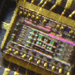
no real progress since last post a few days ago, today at a minimum i only fixed the board with the red solder mask issues..
solder mask slightly misaligned..sanded the mask down a bit to expose the copper pads...

monday when i awoke, I was struck down by a super monster mutated bacterial virus hybrid...
maybe its just a severe case of the flu...

ive been bed ridden for the past few days and today im finally moving about..
i hope to be at 80% strength tomorrow where i will be able to continue working on this an get at least the functional beta working in what was suppose to be my full production week..
oops!! i guess we cant always plan on everything to happen as expected..


just when i thought the flu was the only thing making me sick, now i need to reply to Durgan again...

Durgan wrote:Cool! :)
I suppose you don't know the price for the finished product yet, but how much would you be willing to sell like 3 of the chips by themselves for?
the final price range has been stated a few times within this thread...
due to purchasing additional boards and some other last minute items, the cost should go up another few dollars per board...
since this is more of a miscalculation on my part, there is no reason the customer should have to pay to cover my mistakes...
if your interested in learning the price range, please re-read the thread and you will find the answer...

this goal of this project from the beginning has been to:
1. purchase an official component cable (accomplished)
2. map the mx circuit board (accomplished)
3. duplicate the design (accomplished)
4. locate and purchase mx chips (accomplished)
5. improve/test the design (accomplished)
6. build adapter with improvements previously mentioned in this thread ( in progress)
7. provide a cheaper alternative with improvements for GC forever members ( almost in progress)

goal #7 has always been the main focus...
to provide a cheaper alternative to the members of GC-forever...


im my opinion Durgan, if you want to dev, than you can do as i did and purchase a 70-100$ on ebay to begin your dev work
this is the price we pay for dev work, this is why we dev. someone has to eat the initial cost to do dev
i will not sell stand alone chips..especially to you when you cant even seem to understand the limitations of the DOL-101 as i have stated many times over
in my opinion, selling to you would be complete waste of chips that could be put to good use by other members because they want to play in 480p and/or have digital audio.
if i had 100's of chips, then maybe we could come to terms..but i do not have 100's therefore i do not plan on wasting these chips..

you ask for a quote?? a special price??
ok, i got one for you...
flat out price for you and anyone who wants to purchase these chips alone must pay a penalty fee.
the penalty is for taking opportunity from others..the penalty fee is 350$ per stand alone chip
what do i get out of the +300$ markup for the penalty fee?
nothing!!
all penalty fees will be collected upfront and cost applied toward other members purchases..
so if your willing to do the deed for the greater good, help out your fellow GC forever community and pay the penalty fee..
this should lower final price of each remaining component adapter by 10$ each per penalty fee collected..
emu_kidid wrote: beer is like WD40 for megalomaniac's brain, gets the gears moving
>>> BadAssConsoles.com <<<

Image Image Image
User avatar
iggunr
Posts: 84
Joined: Wed Jul 27, 2011 3:33 pm
Location: mx
Contact:

Re: Gamecube component cable

Post by iggunr » Thu Feb 16, 2012 2:44 am

the penalty fee is a nice idea :lol:
hate to admit it but those chips are scarce
Durgan
Posts: 21
Joined: Tue Apr 19, 2011 10:00 am

Re: Gamecube component cable

Post by Durgan » Thu Feb 16, 2012 7:37 am

Wow. What BS. So I can buy one of your finished products, but if I want less than that I have to pay more? Obviously that is ridiculous.

Also, why the fuck do you think you know me well enough to say I would "waste" the chips? That's pretty insulting, and foolish considering how unfounded it is. It's a very simple matter to make a working circuit. I am completely confident in my ability; I have made circuits before, and I have done mods before (on quite a variety of things). I fix things constantly, and I'm even currently attending college for an electronics degree. I actually planned to use the chips, not 'play' with them.

You seem to be basing everything off of my inquiries here on the GC's video, which I've only recently started looking into. Though regardless, my hypotheses are well founded (if they weren't, why did you even attempt any of them?). And never found good reason to believe I'm wrong. You don't even know why your attempt failed. Furthermore, I don't even know what you're referring to that I "can't understand" about the DOL-101. Or are you just trying to insult me further?

Not having parts is the only reason I didn't try it myself.

I came to this modding community to share what I had learned about the standard DAC, as well as learn some more. I've been polite and genuinely interested in these matters. So to end up with a response like this is pretty shitty, to say the least.
User avatar
liquitt
Posts: 1814
Joined: Thu Apr 01, 2010 5:43 am
Location: neverland

Re: Gamecube component cable

Post by liquitt » Thu Feb 16, 2012 8:30 am

Image
please search before you ask - a lot has been discussed already!
(or use google with "site:gc-forever.com *term*")
http://is.gd/MDmZcr

we also have a wiki filled with knowledge
http://is.gd/dX58Rm
Locked